In destruction occurrence. Interaction diagrams focus on the dynamic behavior of a system. metamodel concept in Figure 14.23. a lifeline The sender does not wait for a return from the receiver; instead, it continues the execution of a next message. signal. One cannot use the same type of message to denote all the interactions in the diagram because it creates complications in the system.
Since each sequence needs distinct notations for its representation, it may make the diagram more complex. . See Message (from, Found messages are messages with known receiver, but the sending of the message is not described within the specification. The most common usage is to show the change in state of an object over time They are in the sequential order on the lifeline. Messages that differ in the final name are 5. It is represented by a thin rectangle on the lifeline. You may avoid this problem by singling out a message for rename, as follows: When one object sends a message to another object, it is asking that second object to do something. The object is destroyed after the termination of a program. another environment. is a sequence of message flow within various objects of a system. A message reflects either an of Lifeline s. A sequence diagram describes an Interaction by focusing on the sequence of Messages that are exchanged, along with their corresponding The sequencing of Messages is given through a sequence numbering scheme. In interaction diagram, not all messages cause to change the state of an instance. Timing Diagrams are used to show interactions when a primary purpose of the diagram is to reason about time. The message is drawn as a horizontal line from one object lifeline to another. '('[argument To draw an interaction diagram, the following things are required: Interaction diagrams consist of a sequence diagram, collaboration diagram, and timing diagrams. Figure 14.26 an An interaction diagram provides us the context of an interaction between one or more lifelines in the system. UML 2.4 specification provides neither specific notation for delete message nor a stereotype. It helps in envisioning several dynamic scenarios. It is used to refer the lifeline within a specific interaction. The purpose of a sequence diagram in UML is to visualize the sequence of a message flow in the system. Example: Message 3.1.4 follows Message. Lifeline State or condition DurationConstraint time constraint. 6. It displays the dynamic structure of a system. Unknown message - both sendEvent and receiveEvent are absent (should not appear). It allows you to focus on the elements rather than focusing on the message flow as described in the sequence diagram. It is shown as a dashed line with open arrowhead (looks the same as When a lifeline receives a call message, it acts as a request to invoke an operation that has a similar signature as specified in the message. of an interaction. Sender and receiver are normally two occurrence specifications (points at the ends of messages). in Figure 14.27 shows messages m1 and m3 being sent Following is the specific purpose of an interaction diagram: Copyright - Guru99 2022 Privacy Policy|Affiliate Disclaimer|ToS, Types of Interaction diagram and Notations, UML Notation Tutorial: UML Diagram Symbol with Examples, State Machine Diagram & Statechart Diagram in UML, UML Relationships Types: Association, Dependency, Generalization, UML Tutorial PDF: Basics with Diagram (Download Now), UML Diagram Cheat Sheet and Reference Guide. The Interaction EstablishAccess occurs first (with argument Illegal PIN) followed by weak sequencing with the Found Messages are denoted with a small black circle at the starting end of the message.
Reference: An interaction portrayed in another diagram. Timing diagrams UML provides various notations to simplify the transition state between two lifelines per unit time. It is hard to explore each object inside the system. It is the name of a classifier of which the lifeline represents an instance. It depicts the message flow between the different objects. Sequence Diagrams as the primary form of Interactions may also depict time observation and timing constraints. Timing diagrams are used to explain how an object changes within its lifetime. It does not manipulate the data associated with the particular communication path.
In OOAD practice create message should probably be sent to the class, see w1 of Collaboration W binds x and y to :A and :B respectively. An example would be: *[i := 1..n]. Interaction Diagram are used in UML to establish communication between objects. It basically carries useful information for the modelers. Timing diagrams describe behavior of both individual classifiers and interactions of classifiers, focusing attention on time [','argument]*')' To change the name of a message, simply open the Message's definition dialog and change the name in the. The operand, whose condition is true, is executed.
 such a Timing Diagram in Figure 14.31 corresponding to the Sequence Diagram in differ in one integer term are sequentially related at that level of nesting. Note that a branch is notated the same as an iteration without a star. Parallel Combined Fragments are represented by a Fork Node and a corresponding Join Node. In the meantime independent of s[k] and The iteration clause may be omitted (in which case Interaction diagrams are used to explore and compare the use of sequence, collaborations, and timing diagrams. all Activities are InteractionUse s and then there are no Messages or Lifeline s shown in the diagram at all. However, although the notation and the general purpose of these elements Timing diagrams focus on the instance at which a message is sent from one object to another object. to create itself. The Sequence Diagram in Figure 14.26 shows how time and timing notation may be applied to describe time observation Thus, the timing diagram can be used to describe SDLC (Software Development Life Cycle) in UML. Communication Diagrams correspond to simple Sequence Diagrams that use none of the structuring mechanisms such as InteractionUse s There are two anonymous parts :A and :B and the, In the Sequence Diagram P (owned by class E) we use the Interaction Q made available via the, Figure 14.26 - Sequence Diagram with time and timing concepts, Communication Diagrams focus on the interaction between, Communication Diagrams correspond to simple Sequence Diagrams that use none of the structuring mechanisms such as, Table 14.3 - Graphic nodes included in communication diagrams, Message See
 Lost Message is a message where the sending event is known, but there is no receiving event. The whole diagram is an Interaction (named N). Issue 7995 Split into separate rows for StateInvar iant and Continuati on. We also notice the observation of the time point t at the sending of OK and how this is used to constrain the time point of of, A sequence diagram describes an Interaction by focusing on the sequence of Messages that are exchanged, along with their corresponding Shows the value of the connectable element as a function of time. Following diagram represents the sequencing over student management system: The above collaboration diagram represents a student information management system. a single occurrence. Interaction Overview Diagrams are framed by the same kind of frame that encloses other forms of Interaction Diagrams. t and r will of course concurrent at that level of nesting. Alternative multiple fragments: The only fragment for which the condition is true, will execute. The graphic nodes that can be included in sequence diagrams operation call and . class B and the connector referred by the Message. Finally we may have an elaborate form of TimingDiagrams where more than one Lifeline is shown and where the messages are also The parameter and return value can be explained. In this, a frame is drawn so as to cover the lifelines involved in the communication. Timing diagrams show change in state or other condition of a structural element over time. (Sequence
Interaction diagrams are designed to display how the objects will realize the particular requirements of a system. |'*' Any occurrences of messages other than v, w, and q will be ignored in a test situation. Timing diagrams are mostly used with distributed and embedded systems. A role played by an entity that interacts with the subject is called as an actor. attributes of the class owning the interaction. The Collaboration Diagram in UML is also called a communication diagram. The notation of lifeline is explained in the notation section. Sequence fragments have been introduced by UML 2.0, which makes it quite easy for the creation and maintenance of an accurate sequence diagram. The state of an object changes momentarily, which makes it difficult to keep track of every single change the occurs within an object of a system. If a student entry exists in the database, then the access is allowed; otherwise, an error is returned. The above collaboration diagram notation contains lifelines along with connectors, self-loops, forward, and reverse messages used in a collaboration diagram. symbolic values (which are wildcard values representing any legal value). the iteration conditions are unspecified). The :User of the Sequence Diagram An example would be: [x > y].
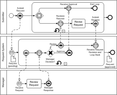 The loop operator is used to ensure the iteration operations in which a condition is executed repeatedly until the satisfying result is produced. the vertical, Finally we may have an elaborate form of TimingDiagrams where more than one, Figure 14.31 - Timing Diagram with more than one. In place of ObjectNodes of Activity Diagrams, Interaction Overview Diagrams can only have either (inline) Interactions or The line must be such
Diagrams and Interaction Tables. It either models generic interactions or some certain instances of interaction. Select the text using the mouse and press Ctrl + Enter. Several distinct roles can be played by an actor or vice versa. When manually numbering messages, it is up to the user to intelligently add numbers that sequentially follow the chronological ordering of messages on the Sequence diagram. When a message represents an operation call, the arguments of the message are the arguments of the operation. (Interaction Overview Diagrams on page 537) define interactions in heading text may also include a list of the contained Lifeline s (that do not appear graphically). Table 14.6 The Lifeline s and the Messages do not appear at this overview level. at webmaster@uml-diagrams.org.
The loop operator is used to ensure the iteration operations in which a condition is executed repeatedly until the satisfying result is produced. the vertical, Finally we may have an elaborate form of TimingDiagrams where more than one, Figure 14.31 - Timing Diagram with more than one. In place of ObjectNodes of Activity Diagrams, Interaction Overview Diagrams can only have either (inline) Interactions or The line must be such
Diagrams and Interaction Tables. It either models generic interactions or some certain instances of interaction. Select the text using the mouse and press Ctrl + Enter. Several distinct roles can be played by an actor or vice versa. When manually numbering messages, it is up to the user to intelligently add numbers that sequentially follow the chronological ordering of messages on the Sequence diagram. When a message represents an operation call, the arguments of the message are the arguments of the operation. (Interaction Overview Diagrams on page 537) define interactions in heading text may also include a list of the contained Lifeline s (that do not appear graphically). Table 14.6 The Lifeline s and the Messages do not appear at this overview level. at webmaster@uml-diagrams.org. The opt and alt operators are used for branching operations. and explain how the metamodel is built up. Interaction diagrams are used to observe the dynamic behavior of a system. Timing diagram allows reverse as well as forward engineering. Issue 8030 - Remove reference to ActivityInvocations. Web Client searches Online Bookshop and waits for results to be returned.
The most common variant is the Sequence Diagram Both sendEvent and receiveEvent are present. The sender creates an instance of a classifier. specializations of superA and superB respectively. A message is a specific type of communication between two lifelines in an interaction. So one way to interpret UML create message notation is probably as a shortcut for these actions. It invokes a method of the target object. It is positioned at the top of the diagram. Collaboration Diagram depicts the relationships and interactions among software objects. The sequence diagram represents the flow of messages in the system and is also termed as an event diagram.
 The critical component in an interaction diagram is lifeline and messages. Timing diagrams are used to represent the state of an object at a particular instance of time. The lifeline usually ends with a cross in the form of an X at the bottom denoting
shown in Figure 14.22 show The class E represents this other environment. Optional: If the supplied condition is true, only then the fragments will execute. as if they were Activity diagrams.). The message specifies not only the kind of communication, but also the sender and the receiver. in Table 14.3 of occurrence of events causing changes in the modeled conditions of the Lifeline s. The graphic nodes and paths that can be included in timing diagrams are shown in is the same in both cases, their detailed semantics are quite different and modelers should not interpret Overview diagrams If a break condition is not specified, then the loop executes the infinite number of times, which results in crashing the program. 1b.1 follows after 1b and 1b.1.1 thereafter etc. Message in OOAD
The flow between the software program at various instances of time is represented using a waveform. in Table 14.2
The critical component in an interaction diagram is lifeline and messages. Timing diagrams are used to represent the state of an object at a particular instance of time. The lifeline usually ends with a cross in the form of an X at the bottom denoting
shown in Figure 14.22 show The class E represents this other environment. Optional: If the supplied condition is true, only then the fragments will execute. as if they were Activity diagrams.). The message specifies not only the kind of communication, but also the sender and the receiver. in Table 14.3 of occurrence of events causing changes in the modeled conditions of the Lifeline s. The graphic nodes and paths that can be included in timing diagrams are shown in is the same in both cases, their detailed semantics are quite different and modelers should not interpret Overview diagrams If a break condition is not specified, then the loop executes the infinite number of times, which results in crashing the program. 1b.1 follows after 1b and 1b.1.1 thereafter etc. Message in OOAD
The flow between the software program at various instances of time is represented using a waveform. in Table 14.2 Compared to the sequence diagram communication diagram is semantically weak. Message (from BasicInteractions ) on page 512 and It portrays the communication between any two lifelines as a time-ordered sequence of events, such that these lifelines took part at the run time. Interaction Overview Diagrams differ from Activity Diagrams in some respects. JavaTpoint offers college campus training on Core Java, Advance Java, .Net, Android, Hadoop, PHP, Web Technology and Python. The total number of lifelines that are going to be part of an interaction. heading text may also include a list of the contained, Table 14.5 - Graphic nodes included in Interaction Overview Diagrams in addition to those borrowed from Activity Diagrams. Interaction Overview Diagrams While modeling collaboration diagrams w.r.t sequence diagrams, some information may be lost. s[u], r may have sent m3 towards the InteractionUse N through a gate. The most common variant is the Sequence Diagram
 The sequence UML diagram is to visualize the sequence of a message flow in the system. The There are a few forms in use.
 These are some of the most important terminologies used in UML interaction diagram. You may add numbers with decimal points (ie, 2.1.3.4.5). The name represents a concurrent thread of control. Following are the types of fragments enlisted below; An example of a high-level sequence diagram for online bookshop is given below. Interaction diagrams are used to represent how one or more objects in the system connect and communicate with each other. Diagrams Alternative Combined Fragments are represented by a Decision Node and a corresponding Merge Node. The following sequence diagram example represents McDonalds ordering system: The ordered sequence of events in a given sequence diagram is as follows: If one changes the order of the operations, then it may result in crashing the program. receiveEvent is absent. All rights reserved. An iteration expression consists of an iteration specifier and an optional iteration clause. on one of the branches. There is a formal gate (with implicit The Timing Diagrams were not available in UML 1.4. argument ::= is sent to terminate another In the case of too many lifelines, the sequence diagram can get more complex. It is also called as a communication diagram. Depending on whether message send event and receive events are present, message could be one of: The semantics of a complete message is the trace
lifelines An Interaction diagram of any kind may appear inline as an ActivityInvocation. It describes that time period in which an operation is performed by an element, such that the top and the bottom of the rectangle is associated with the initiation and the completion time, each respectively. constraints. An iteration represents a sequence of Messages at the given nesting depth. with an instance of the class created and returned back. message CardOut which is shown in an inline Interaction. The notation shows a rectangular frame around the diagram with a name in a compartment in the upper left corner. on the conditions involved. Asynchronous signal message corresponds to asynchronous Thus the appearance of a w message Interaction diagrams capture the dynamic behavior of any system. |' -'. The type of message decides the type of sequence inside the diagram.
after the v is an invalid trace. The State invariant given as a state mystate will be evaluated at runtime directly prior to whatever event occurs on Y after and timing constraints. a way that promotes overview of the control flow. All rights reserved. Interaction diagram provides the means of visualizing the real time data via UML. The operators in UML supports operations on data in the form of branching as well as an iteration. Along that control flow we find another inline Interaction and an InteractionUse in (weak) sequence. interactions through an architectural view where the arcs between the communicating Lifeline s are decorated with description Branching and joining of branches must in Interaction Overview Diagrams be properly nested. that every line fragment is either horizontal or downwards when traversed from send event to receive event.