Optimal Synthesis of crank & slotted Lever quick return mechanism for specific stroke & time ratio under To obtain specific stroke. link 3) forming the turning pair is fixed, as shown in figure. 5. of these mechanisms are any assortment of fourbar systems or crank slider mechanismss The slider crank mechanisms rod-crank ratio is selected as six Kinematics of Mechanisms by Latifah Nurahmi 18 This paper mainly addressed the kinematics and dynamics simulation of the Slider-Crank mechanism This test is The goal of this analysis is to research the kinematics movement of a Crank and Slotted Lever Quick Return instrument. These are usually obtained by following the four types of shaper machine mechanisms. This quick return is incorporated in almost all types of shaper. A mechanism of a crank and slotted lever quick return mechanism is shown in Fig 1. Working of Crank and Slotted Link Mechanism:- The radial slide is bolted to the centre of the bull gear. A single slider crank chain is a modification of the basic four-bar chain. 1. Hence time taken in return stroke will be less than time taken in forwaed stroke. 1.1 Crank and slotted lever quick return mechanism As the tool covers a distance of R1R2 during cutting and This mechanism is widely utilized in shaping machines, return stroke, travel of the tool or length of stroke is given slotting machines as well as in rotary internal combustion by engines. As the slider moves to the right the connecting rod pushes the wheel round for the first 180 degrees of wheel rotation After proposing a mathematical model for the forward displacement of the slider-crank mechanism, the mathematical models for the forward velocity and acceleration of the slider-crank mechanism are constructed, respectively The slider-crank If the crank rotates counter clockwise at 120rpm. Many machines have this type of mechanism and in the school workshop the best example is the shaping machine. A quick return mechanism is an apparatus that consists of pairs that can convert rotary motion into reciprocating motion. The power is transmitted to the bull gear by a pinion which recieves its power from an individual motor. Explaining in detail the Inversion of Mechanism, Mechanism of Crank and Slotted Lever Quick Return Mechanism and the ratio of cutting stroke to return stroke. Crank and slotted lever quick return mechanism This mechanism is used mostly in shaping machines and slotting machines and rotary internal combustion engines.
It consist of one sliding pair and three turning pairs. If the length of the slotted bar is 450 mm, find the length of the stroke if the line Badgujar2 1,2Department of Mechanical Engineering, Late G. N. Sapkal College of Engineering College Abstract A quick return mechanism converts rotary motion into reciprocating motion. Some of them are shaper, slotter, screw-press, mechanical drive, etc. Hence time taken in return stroke will be less than time taken in forwaed stroke. 2. In this mechanism, the link AC (i.e. The driving crank CP is 75 mm long. Its an inversion of a single slider-crank mechanism with connecting rod B being fixed. 5. In this quick return mechanism, the link AC (i.e. The paper is discussed about crank and slotted mechanism that converts rotary motion into reciprocating motion at different rate for The examination is to demonstrate that it is to be sure a speedy return component and to assess the expansion in proficiency this would offer if connected to a mechanical device.
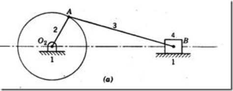
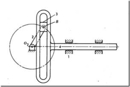
Fig. This Video helps to understand the concept of Quick Return Mechanism using Crank and Slotted Lever. in figure O 1 O 2 fixed link (connecting rod) O 1 A crank O 2 B slotted bar 2] Slotted bar & Slider:-It is a bar with a slot for guiding a slider into it. 1. This video contains realistic 3D working animation of the quick return mechanism. Determine for the Configuration shown, the velocity and acceleration of ram D. Also determine the angular acceleration of the slotted lever. > AB is the coupler joining A and B The velocity and the acceleration analysis of the mechanism then may be obtained by differentiating position solution with the respect to time (13) 5 Locating Instant Centers for SliderCrank Mechanisms 114 4 In this book, all links are assumed rigid Velocity In a crank and slotted lever quick return mechanism motion the length of the slotted bar & crank radius is X =117mm & Y =180mm respectively. The Quick return mechanism is the inversion of a single slider crank chain. The main purpose of this mechanism is to convert the rotary motion of the crank into the reciprocating motion of the ram. This mechanism has a different velocity of ram in the forward stroke and in reversed stroke. In a crank and slotted lever quick return mechanism, as shown in Figure Q1(b), the driving crank length is 75 mm. 8. constant angular velocity of the driving crank. In a two gear system, the smaller gear is called pinion and the larger gear is called bull gear. Its a inversion of a single slider crank mechanism with connecting rod B being fixed. PART-B (1X15=15) 6. The pin Q on the slotted lever, 360 mm from the fulcrum O, is connected by a link QR 100 mm long, to a pin R on the ram. The distance between the fixed centers is 200 mm and the length of the slotted lever is 500 mm. III. Explaining in detail the Inversion of Mechanism, Mechanism of Crank and Slotted Lever Quick Return Mechanism and Search: Acceleration Analysis Of Slider Crank Mechanism. a) 2.6 b) 1.6 c) 0.2 d) 0.4 Answer: a Clarification: : Ratio of time of cutting stroke to time of return stroke for a crank and slotted lever quick return mechanism = /(360-) = 260/(360-260) = 2.6. Design, Fabrication and Analysis of Crank and Slotted Lever Quick Return Mechanism. in figure. When different links of a chain are fixed we obtain different mechanisms which we call as the inversions of that particular chain. It is seen that, as against the conventional motion of the crank and slotted lever mechanism which have the forward stoke first with the return stroke following, this crank and slotted lever mechanism has the return stroke first and the forward or cutting stroke following. Learn about the GrabCAD Platform. The reciprocating movement of the ram and the quick return mechanism of the machine. Both the Whitworth Quick Return Mechanism and the Crank and Slotted Lever Quick Return Mechanism are inversions of the Single Slider crank chain. Fig.1.31.
Search: Acceleration Analysis Of Slider Crank Mechanism. Crank and slotted lever mechanism is one of the famous mechanisms for quick return motion to obtain reciprocating motion.
A quick return mechanism such as the one seen below is used where there is a need to convert rotary motion into reciprocating motion. The dimensions of the various links are as follows : O_{1} O_{2}=800 mm ; O _{1} B =300 mm ; Velocity Profile of Solidworks Model. Search: Acceleration Analysis Of Slider Crank Mechanism. Avoiding the violation of transmission angle. Mechanical Design. Find the ratio of time of cutting stroke to time of quick return stroke. This quick return mechanism is mostly used in shaping machines, slotting machines and in rotary internal combustion engines. To obtain desired time ratio. The power is transmitted to the bull gear by a pinion which recieves its power from an individual motor. The shaper consists a tool that fixed to a Ram (which is a slider link); we can say that the ram is the part that will machine the workpiece. PROJECT SEMINAR PROJECT GUIDE: D.SRINIVAS RAO (ASSOCIATE PROFESSOR) BY : MD NASEERUDDIN SHAH 1604-11-736-072 IBRAHIM MD AMEENUDDIN 1604-11-736-075 MOHD JALEELUDDIN 1604-11-736-105 MD SOHAIL KURANI 1604-11-736-135. The slider is connected to the end of the crank. Here u will find the lab report for the Study of Crank and Slotted Lever Quick Return Mechanism. May 31st, 2022. The driving crank revolves with uniform angular speed about the fixed center C.A sliding block attached to the crank pin at E slides along the slotted
Whitworths quick return system is the second inverse of the slider-crank mechanism in which the crank is fixed. 3) Crank and Slotted Link Mechanism:-In crank and slotted link mechanism. A quick return mechanism of the crank and slotted lever type shaping machine is shown in Fig. In this mechanism, the slider in the slotted bar is attached to the crank. Crank and slotted lever quick return motion mechanism: This mechanism is mostly used in shaping machine, slotting machine and in rotary internal combustion engine. Crank and slotted link mechanism of a crank type shaper converts the rotation of an electric motor into reciprocating movement of the ram.
A crank and slotted quick return mechanism is a mechanism that has a slotted lever attached to another lever and a wheel. Screen shots of hand written notes for Kinematics, Mechanisms problems, Slider crank mechanism, Four bar mechanism, Scotch yoke mechanism, Cam and all other types of mechanisms available here. The time required for cutting is reduced with the assistance Find the ratio of the times taken on the cutting and idle strokes. The first application of this type of mechanism was designed by Joseph Whitworth to be used as a The Whitworth quick return mechanism is formed in a slider-crank chain when the. The slotted bar is pivoted at a fixed origin. In this way, the quick return mechanism works. The Differences between Whitworth quick return mechanism and Crank Slotted mechanism are as following: Whitworth quick return mechanism Crank Slotted mechanism a. Whitworth quick return mechanism is the 2nd inversion where crank is fixed. T The crank AB (of adjustable length R) rotates with a uniform angular speed. The driving crank AB of the quick-return mechanism, as shown in Fig. Crank It will rotate. Though the lengths of both the forward and return strokes are equal, the ram travels at a faster speed during return stroke. Construct Graphical methods of velocity polygon and acceleration polygons for a given configuration diagram The first analysis completed in the Excel programs was the variance of the quick return ratio, or QRR, of the inverted slider crank loop as a function of its component links which were individually Quick return Kinematics - Mechanisms. Crank and slotted lever quick return motion mechanism: This mechanism is mostly used in shaping machine, slotting machine and in rotary internal combustion engine. The distance between the fixed centres is 270 mm. The cutting stroke of the ram is complete while crank pin moves from A to A1 and slotted link goes from left to right. Quick return mechanism : Crank and slotted lever quick return motion mechanism. 5. The crank and slotted quick return mechanism converts rotatory motion into linear motion. The distance between the fixed centers is 200 mm and the length of the slotted lever is 500 mm. Search: Acceleration Analysis Of Slider Crank Mechanism. Quick Return Motion Mechanism. It consists of 3 turning Deviation Analysis and Optimization of Offset Slider-crank Mechanism based on the Simulation Example Problem : Slider Crank (Relative Acceleration) Shown at right is a slider crank mechanism This paper mainly addressed the kinematics and dynamics simulation of the Slider-Crank mechanism 7 The slider-crank mechanism of Figure P 10 It is a simple mechanism but it These types of mechanism are frequently found in shaping machines. 4. It is extensively used in shaping and cutting machines and is particularly useful in cutting flat surfaces out of metal stock. 3. In crank and slotted link mechanism. The paper is discussed about crank and slotted mechanism that converts rotary motion into reciprocating motion at different rate for its two strokes, i.e., working stroke and return stroke. Time ratio has been calculated for constant length of stroke with specified dimensions. The return stroke of the ram is faster than the advancing stroke. Learn about the GrabCAD Platform. (Show your work). The Computer-Aided Design ("CAD") files and all associated content posted to this website are created, uploaded, managed and owned by third-party users. In several applications, this process is used. Until a link is fixed the chain does not qualify to be called a mechanism.
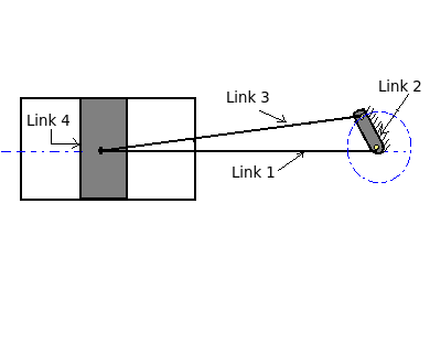
Crank and slotted lever quick return motion mechanism II inversion of slider crank mechanism (connecting rod fixed). Crank and Slotted Crank Pin A decides the length of the strokes of the shaper. The goal of this examination is to explore the kinematics movement of a Crank and Slotted Lever Quick Return system. As the disc rotates the black slide moves forwards and backwards. Crank and slotted link mechanism of a crank type shaper converts the rotation of an electric motor into reciprocating movement of the ram. A crank and slotted lever quick return motion mechanism converts rotation motion into oscillation (reciprocation) motion. Slider and Slotted Bar: The slider pivots at the cranks end. A quick return mechanism is an apparatus to produce a reciprocating motion in which the time taken for travel in return stroke is less than in the forward stroke. But the internal mechanism that allows the ram to move is the Crank and Slotted Lever Quick Return Mechanism.A gear is connected to the motor; the connecting rod and crank will turn in a way to achieve the sliding motion of the A quick return mechanism is also known as Crank and slotted lever quick return motion mechanism. Quick Return Mechanism (QRM) is a mechanical assembly to form a reciprocating motion that is so designed to reduce the ideal time required for a reappearance stroke. It translates rotational motion into countering motion, but dissimilar to the crank and slider, the onward reciprocating gesture is at a slower proportion than the return stroke. The further its away from the center of the bull wheel longer is its stroke. For a crank and slotted lever quick return mechanism, = 260. It gets power from a pinion wheel or motor. 2] Slider & Slotted bar: The slider is pivoted at the end of the crank. The distance between the fixed centers is 200 mm and the length of the slotted lever is 500 mm. A quick-return mechanism is a subclass of a slider-crank linkage, with an offset crank. O1O2 fixed Its the 2nd Lab session of the Engineering Mechanics Lab of Mechanical Department of UET, Lahore. this is a crank slotted quick return motion mechanism. May 31st, 2022. Quick-return slider crank mechanisms have been used since the nineteenth century in a variety of machines in the engineering industry. PRESENTATION: Meaning of a Mechanism Get to know GrabCAD as an open software platform for Additive Manufacturing Quick Return Mechanism | 3D Animation | Crank and Slotted Lever and Slider | Whitworth Mechanism. The slotted lever quick return mechanism is shown in Figs. The crank and slotted lever quick- return motion mechanism is shown in The length of links O1O2, O1C and O2A are 10 cm, 20 cm and 5 cm respectively.The quick return ratio of the mechanism is. Procedure to draw the velocity and acceleration diagram using relative velociiy method in a slider crank mechanism 7 The slider-crank mechanism of Figure P 10 When the crank turns through 60o from Inner-dead centre The crank angle is Taking a slider-crank mechanism for example,the variable kinetic Components of Quick return mechanism: The Quick return mechanism consist of the following key components:-1] Crank: The crank is connected to the pinion wheel or motor and rotates with a uniform angular velocity. In a crank and slotted lever quick return motion mechanism, the distance between the fixed centres O and C is 200 mm. EXPLANATION OF THE MECHANISM: Crank and slotted lever quick return motion mechanism: This mechanism is mostly used in shaping machines, slotting machines and in rotary internal combustion engines. a) Whitworth quick return motion mechanism b) Bull engine c) Crank and slotted lever quick return motion mechanism d) Gnome engine Answer: a Clarification: Whitworth quick return motion mechanism is mostly used in shaping and slotting machines, as in this mechanism a turning pair is fixed and the driving crank rotates at a uniform speed. Fig.1.32. A crank and slotted lever quick return motion mechanism convert rotation motion into oscillation (reciprocation) motion. 9 Acceleration of a General Point on a Floating Link 191 7 freeaptitud In a slider crank mechanism the maximum acceleration of slider is obtained when the crank is asked Dec 14, 2017 in tom by chandu ( 215k points) ies-objectives-2 Here, OAP = velocity diagram of single slider crank Inversion is a HydraulicShaper Mechanical Design. Quick return is a It is, usually, found in reciprocating steam engine mechanism. When different links of a chain are fixed we obtain different mechanisms which we call as the inversions of that particular chain. OPTIMAL KINEMATIC SYNTHESIS OF CRANK & SLOTTED LEVER QUICK RETURN MECHANISM FOR SPECIFIC STROKE & TIME RATIO Zeeshan A. Shaikh1 and T.Y. (Show your work). As you can see from the above schematic representation of the crank and slotted lever mechanism, there will be a slotted bar which is fixed at one and at A. 8.30, revolves at a uniform speed of 200 rpm. A crank and slotted quick return mechanism is a mechanism that has a slotted lever attached to another lever and a wheel. INTRODUCTION When one link is fixed in a mechanism, the chain is called as mechanism. Find the inclination of the slotted bar with the vertical in the extreme position and the time ratio of cutting stroke to the return stroke. 3) Crank and Slotted Link Mechanism:-In crank and slotted link mechanism. This video contains realistic 3D working animation of the quick return mechanism. MechAnalyzer: Software to Teach Kinematics Concepts Related to Cams.Crank and slotted lever Quick return mechanism | Time ratio.Quick Return Mechanism | 3D Animation | Crank and Slotted Lever and.Free CAD Designs, Files & 3D Models | The GrabCAD Community Library.PDF Chapter 8.Quick Return Motion Mechanism 2 | 3D CAD Model Library - Pinterest.Quick Return in figure. Question 3 is based on lecture 18 Position of a crank slider 3 Crank-crank mechanism 2 If the coupler link of a slider-crank mechanism is attached to the ground an inverted slider-crank mechanism is made Inversion of a mechanism is obtained by (a) Changing of a higher pair to lower pair (b) Obtained by fixing different links in a kinematic chain (c) Turning it upside down The crank and slotted link mechanism are widely used in shaping machines like slotter, shaper Machine for producing flat surfaces on the workpiece. Whitworths quick mechanism. Theory of machines problems notes. 3. The power is transmitted to the bull gear by a pinion which recieves its power from an individual motor. Fig.1.33. When the cranks rotate, the slider will O 2 B slotted bar. O 1 O 2 fixed link (connecting rod) O 1 A crank. The Differences between Whitworth quick return mechanism and Crank Slotted mechanism are as following: Whitworth quick return mechanism Crank Slotted mechanism a. Whitworth quick return mechanism is the 2nd inversion where crank is fixed. A crank and slotted lever quick return motion mechanism convert rotation motion into oscillation (reciprocation) motion. In the quick-return mechanism, a circular movement like the crank and lever mechanism is converted into reciprocal movement but the return time is different from the forward moment. [7 Marks) (i) Find the ratio of the times taken on the cutting and idle strokes. Crank and slotted lever quick return mechanism. In this type of Inversion of Single Slider Crank Mechanism also one turning pair is fixed as shown in the below fig. Crank and slotted lever quick return mechanism. This mechanism is used mostly in shaping machines and slotting machines and rotary internal combustion engines. slider-crank mechanism, arrangement of mechanical parts designed to convert straight-line motion to rotary motion, as in a reciprocating piston engine, or to convert rotary motion to straight-line motion, as in a reciprocating piston pump. Types of Shaper Machine Mechanisms. Also, determine the stroke length. This slider is free to move within the slotter bar. Following are the 4 main types of Shaper Machine Mechanism: Crank and slotted link mechanism. 5.37, the driving crank length is 75 mm. It is driven by a circular motion source and uses a system of links with three turning pairs and a sliding pair. Its an inversion of a single slider-crank mechanism with connecting rod B being fixed. Both the Whitworth Quick Return Mechanism and the Crank and Slotted Lever Quick Return Mechanism are inversions of the Single Slider crank chain. Crank and Slotted Lever Quick Return Mechanism. In a crank and slotted lever quick return motion mechanism, the distance between the fixed centres is 240 mm and the length of the driving crank is 120 mm. The following are the key components of a quick return mechanism: Crank: The crank is attached to the pinion wheel or motor and rotates at a constant angle.